

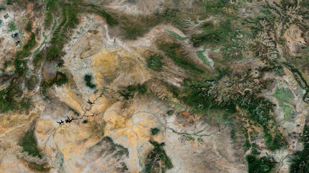
- Pure TruEarth Color
- Global 15-meter Mid-Resolution Basemap
- Web Maps | Simulation | Visual Effects
TruEarth® Satellite Imagery
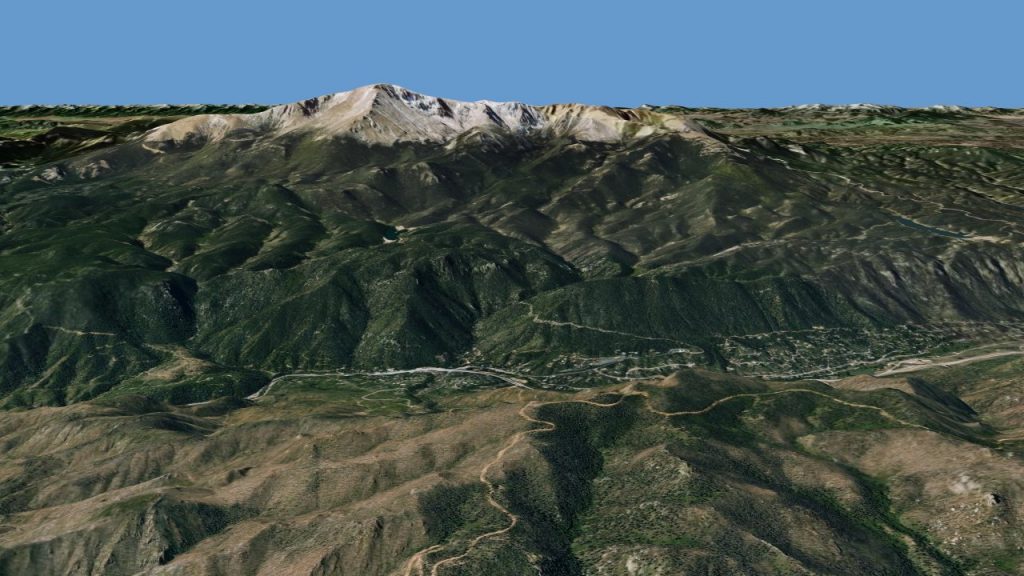
nScape™ 3D Terrain Engine
- Compact, Multi-Platform, Mobile/Desktop
- Compressed Global Terrain and Imagery
- SVS | Flight Planning | Simulation
TruEarth Imagery and nScape 3D Rendering Can Take You Anywhere!
FAQs
About Us
TerraMetrics provides cost-effective satellite imagery, 3D terrain datasets and 3D terrain-rendering software tools to the computer visualization, simulation, mapping and animation markets. We have experience working with the some of best customers in the world.